
Make your own walking bike

This is a step by step guide of how to make your own walking bike. The bike is a mixture of a treadmill, a traditional bicycle, and a scooter. The resulting product is fun and easy to ride the bike that is propelled by the energy produced by moving forward on the track of the bike itself! The bike is extremely efficient and healthy for people who ride it. The versatile design makes it an easy and fun rife for people of all ages. Follow this free guide and you can build your own!
Gather the parts
The walking bicycle is an assembly of a lot of parts including
a lot of major electrical components and other essentials.
The electrical components are:
Motor.
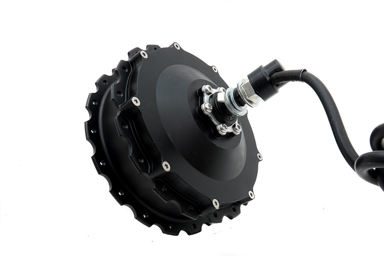
This is a 250w 36v brushless hub motor. The specialty of this kind of motor is that its an outrunner. Meaning that its inner coil is stationary and the outer body rotates. This motor is supposed to be 96% efficient.
Controller.
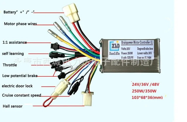
This is a 36v brushless motor controller. It’s capable of handling current up to 40A. This is the main component of the electronic system as it controls the speed of the motor which again determines the speed of the bike.
Battery

The battery I’ve used for this walking bike project is a 36v 7.2A lithium-ion battery. The battery is also a major component of the bike. The lithium-ion batteries cost a lot but are definitely worth the price as they can charge way faster than the traditional lead-acid batteries and have a thousand times more recharge capacity. All these benefits and still 1/4th the weight and size. There are cheaper alternatives available which you can use to reduce the cost of the project but I wouldn’t recommend it as it would drastically increase the weight of the bike and make it very difficult to balance. A lithium-ion battery is definitely the best choice but you can always be creative with your own ideas.
Brake levers.

These brake levers have a tiny switch between the liver and the coupler that play a very vital role. When the liver is pulled it signals the controller to cut off the power supply to the motor. That results in making the walking bike very safe and easy to stop.
Throttle.
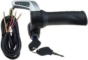
The throttle is basically based on a simple three-pin potentiometer encased in a user-friendly body. The throttle also acts as a battery level indicator by dividing the battery charge into four units. The full charge of the battery is indicated by a green light which reduces to yellow and then red with the gradual consumption.
Some extra components that will be needed for the bike are
Charging socket - female 
A power cut switch.

Wire

The material required for the fabrication of the bike :

I’ve used a 19.5-foot long cylindrical pipe to fabricate the rollers on which the belt moves. Well, this is where you have to get creative. For my case, I’ve used the bearing of side “6202” for the rollers. So I took a pipe that was roughly the size of the bearings but falls a bit short on diameter.
I also used different sizes and lengths of square and rectangle pipes to construct the frame of the bike
The essentials
1x 13*76” high-quality treadmill belt. ( do not go for cheaper alternatives )

2x 16” wheels (with Tyre tubes and hub installed.)

1x front paddle gear
1x handlebar

1x front shock absorber.

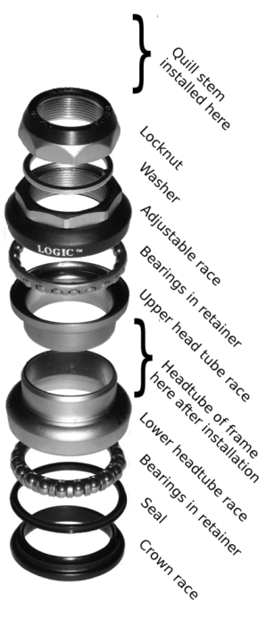
1x front neck bearing set assembly
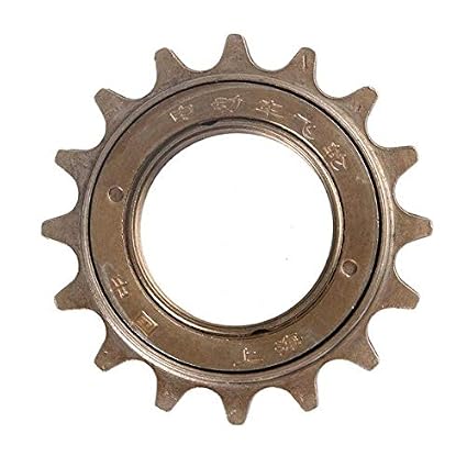
4x freewheels
2x cycle chains.

2x disc brakes
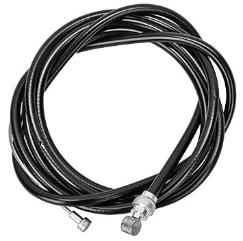
2x brake wires
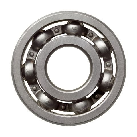
36x 6202 size bearings
2x 6002 bearings.

36x 25mm bolts with nuts and 1mm washers.
//I’ve also used a lot of different sized washers according to the need in different situations that came up during the build.
START BUILDING
The roller frame.
So just like an ordinary treadmill belt is supposed to move freely but in this case, since we have to use the energy generated by propelling the belt we can not afford to lose energy thereby the traditional way of sliding the belt over a slippery wooden platform is not the best idea. So instead I’ve used a roller based frame.
The adjustment of the belt’s tension is done by tightening or losing the front roller. For that, a tiny “C” channel is welded over a strong 3*1” pipe which acts as a major supporter to the frame.


As shown in the picture the shaft of the cylinder is adjustable as it moves front and back as is adjusted by an Allen screw.
To make the rollers I cut out the long cylindrical pipe into 18 pieces of 13 inch each. I then attached all the pipes separately one by one on a lathe or a milling machine and increased the diameter of the pipe from the inside on both sides to match my 6202 bearings.
For the rest of the rollers, I created a channel by cutting out the back end of a 2*1” pipe and drilled 18 holes of 9mm so the o can insert bolts through them which would act as a shaft for the rollers.
Now after testing the setup I got all the nuts welded onto the channel I made out of the pipes to make is a single piece.


The last roller was put on a milling machine to create grooves for a better grip on the belt. Also, I created a coupler that on one end was joined to the roller and had grooves to install a flywheel on the other end. The roller wasn’t installed to the major supporting pipes by a full-length stainless steel shaft.
Two 15” pipes were welded on the front and the back end of the assembly temporarily to keep the setup in place.

This completes the roller assembly.
Installing the wheels
Now the next step was to install the front and rear wheels to the walking bike. To do that I created a triangular frame on the front end over which I welded a pipe that acted as a neck to hold the handlebar and the front shock absorbers. To create the neck a tool an 8” long hollow cylindrical pipe and milled the bearing set coupler to it. Now the front wheel and the shock absorbers and the handlebar was installed just like a normal bicycle.

For the rear wheel, I fixed two pipes, two to hold the rear wheel in place and two for the motor. I needed the whole system to be very adjustable. So to do that I took 4 pieces of metal plates and I drilled a hole in the plates on the centerline towards the side of the plate. Then I grinded out a cut in the plates by cutting out two straight lines on either side of the hole. This created a channel and passage where my wheels and motor can easily slide. Also, I used motorcycle chain tensioners so that the motor and wheel would stay at the desired position where I tighten it up by their respective nuts.


With both the front and rear wheels installed, the walking bike has started to take shape but there still is a lot of work to do.
Gearing system
The system that transfers the power generated by walking on the walking bike to the rear wheels is created by using 5 gears.
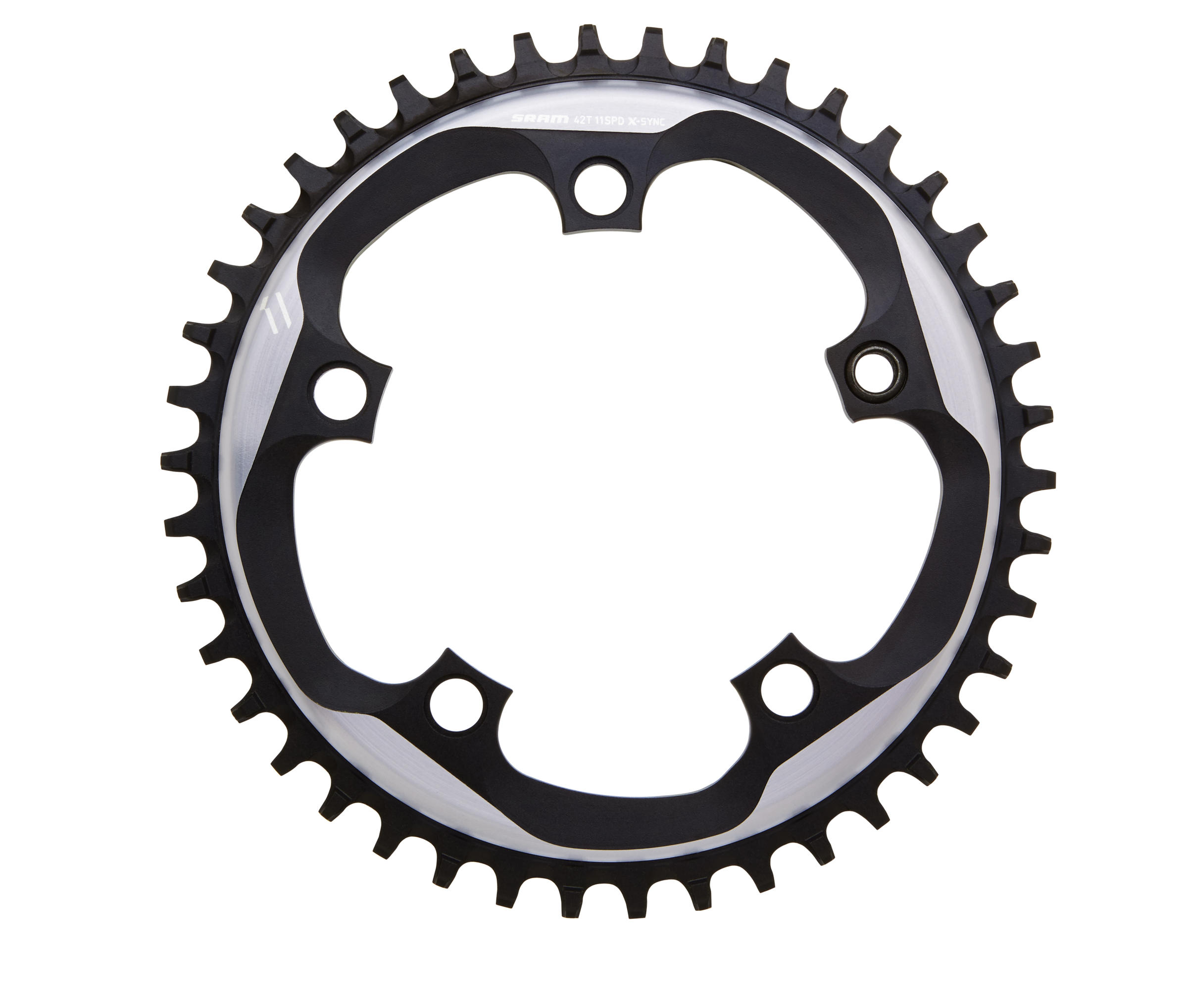
Firstly the big gear is installed over the motor by screws. To do this the gear is put on a milling machine and the inside part of the gear is precisely cut out the gear and that leaves us behind with just a ring with 5 extensions to it. On each of the extractions, a small hole is drilled and after placing the gear on the edge of the motor the same hole is drilled accurately. The hole then serves as a binding spot where small screws are inserted and tightened. The motor is then installed in its fabricated bracket and then a loose chain is pulled over it connecting it to the last roller’s flywheel.
Now for the system to work, we need to change the direction of the rotation as the treadmill belt is moving forward and we need the bike to move forward.

To do that a shaft is created which joins who flywheels on each end. To create this flywheel I used two brackets used in paddle rickshaws that joins the flywheel to the axle of the rickshaws. I joined the two brackets by tightening them over a pipe of the same diameter as of the brackets from the inside. I also got a 6002 bearing milled and fixed inside the brackets. Now the setup we created was installed over the chain connecting the motor to the roller by pressing it over the chain. Now when the motor moves backward the gear wheel just installed moves forward thereby pushing the walking bike forward. The gear on the other end was connected to the wheel by a chain and by this we complete the gearing system.
Battery box
More fabrication was required to make a compartment to store the battery and controller. I used metal sheets to cover the structure.


Now furthermore metal pipes and plates were added to the chassis of the walking bike to reinforce it and to make it robust and also to make the bike look more versatile.


I also added a chrome mudguard over the gearing cover up the gears and to make the walking bike look better.

I added a small bicycle stand to the bike.
By this, we complete the fabrication part.
Electronics
Moving on to the electronics the throttle, brake wires, battery, and the controller are connected and the final testing of the system is done.
Paint
Now to paint it first the walking bike is dismantled and painted with red oxide priming agent to protect it from rust.


And then powder coated in black color.
The walking bike is now complete.


The walking bike is capable of achieving speeds up to 35km/h and has a battery backup of up to 30-50 km depending upon how much effort the person riding is it providing. It took me 16 days to complete the project and it turns out to be satisfactory to my eyes. The bike is robust smooth and fun to ride. It also has a positive impact on the rider's health.
I believe there’s always space for improvements so use this as a guideline and work out your own ideas to create something even better. All the best.
I completed the entire project in 16 days.
Here are some other photos and videos for reference purposes.


That's me. Not so ugly in reality. Dm for rishtas @ojash_101
Do check out my other blog about how to make an electric bike by clicking here!


0 Comments